Installation
Already assembled?
If you have purchased a ready-made KXUSBC2 kit, the hardware assembly is already done for you — start here.
Prerequisites
- Elecraft KX2 transceiver
- 3S (12.6 V) Li-Ion battery (or 4S LiFePO₄ with firmware configuration)
- KXUSBC2 board
- Replacement left side aluminum panel with USB-C opening
- Thermal pad (10 x 6 mm, 4 mm height)
- Heat shrink tube (2.5 x 15 mm)
Optional (if not pre-installed in KX2)
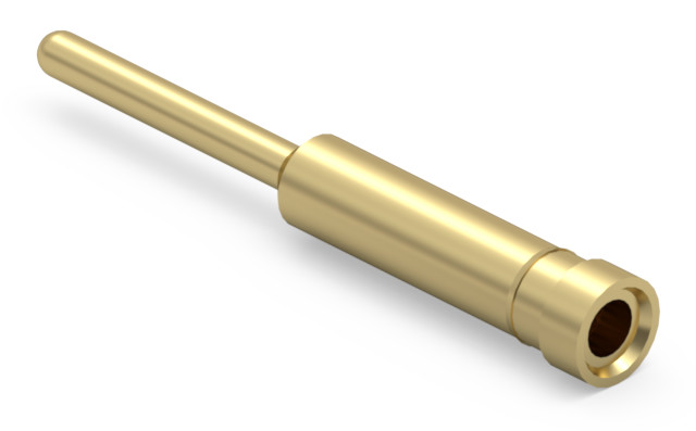
- 2 pcs. receptacle pins (Mill-Max 8827-0-15-15-16-27-04-0)
Preparing the KX2
Skip this section
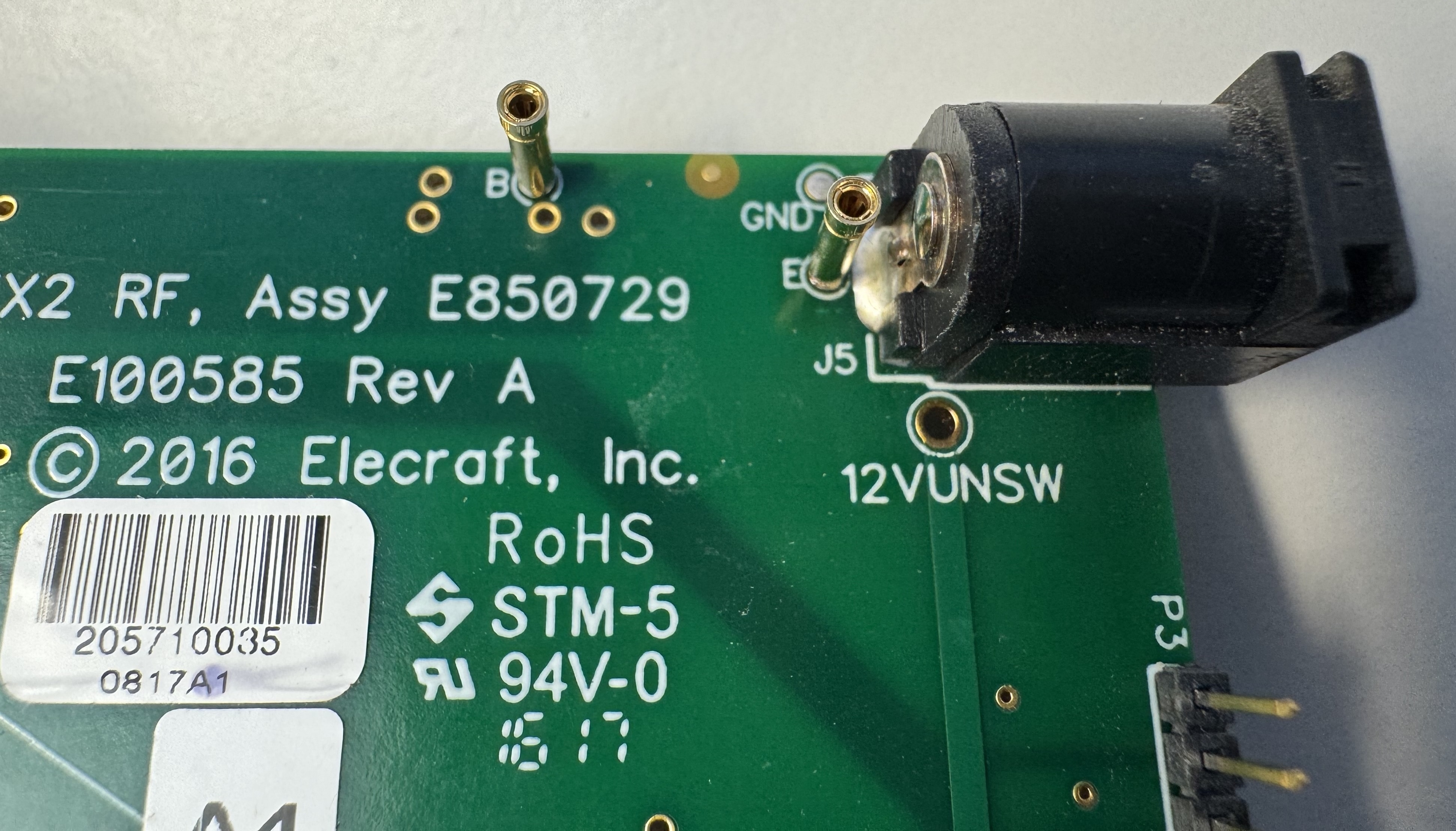
Skip this section if your KX2 already has receptacles on the B and E pads (newer KX2, or if you've installed a KXIBC2 before).
Solder long, slim gold pin receptacles (Mill-Max 8827-0-15-15-16-27-04-0) to the E and B pads:
- If pads are filled with solder, pre-heat with hot air and use solder wick
- The RF PCB can be removed for easier soldering on the bottom, or soldered in place
A simpler method (which makes removal more difficult, however) is to skip the receptacles, and instead solder the pins from the KXUSBC2 directly to the B pad and the DC jack's center pin.
See the KXIBC2 installation guide for a detailed explanation of both methods.
Hardware installation
- Remove the KX2 back cover
- Unplug and remove the battery
- Unscrew the 4 screws from the left side panel — the longer screws with finer thread will hold the KXUSBC2
-
Connect the power wires:
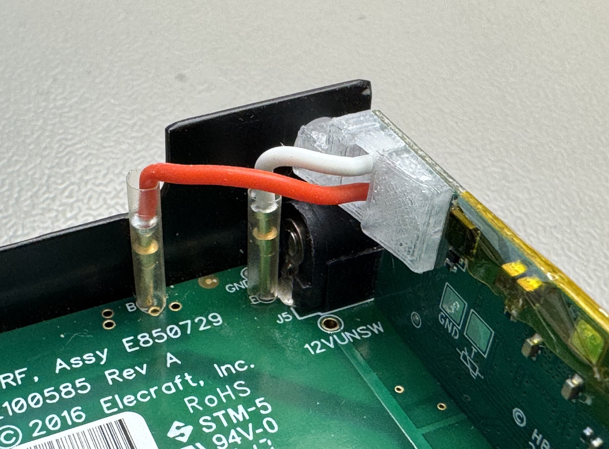
- Slide heat shrink tubing onto the red and white wires (optional on white)
- Plug into the KX2 RF PCB receptacles (E = white, B = red)
-
Slide tubing over the pins (no need to heat shrink)
-
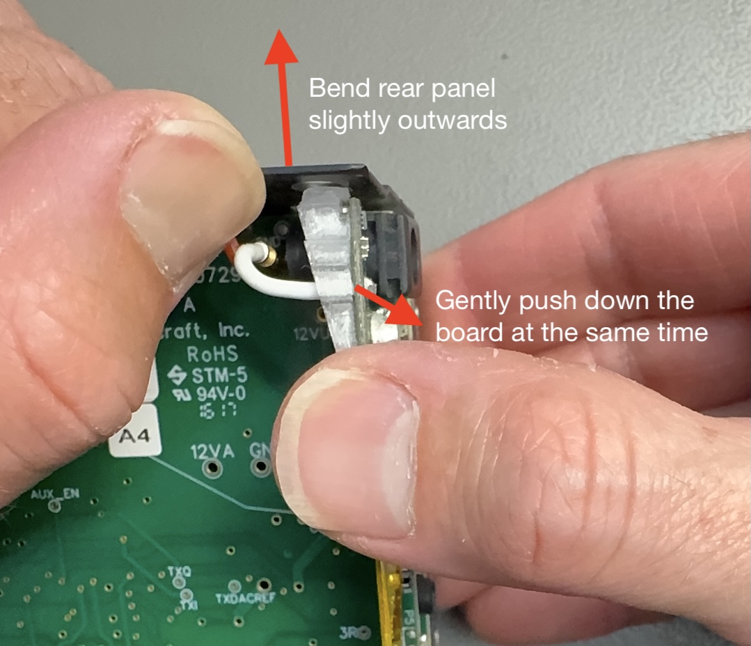
Plug the KXUSBC2 board into the KXIBC2/KXIO2 slot and ensure it's properly seated
Don't force it
Bend the rear panel of the case slightly outwards to let the lens of the LED diffuser slide in. Do not force the board in, or you will break off the diffuser/LED. One of the four connectors at the bottom edge is not used.
-
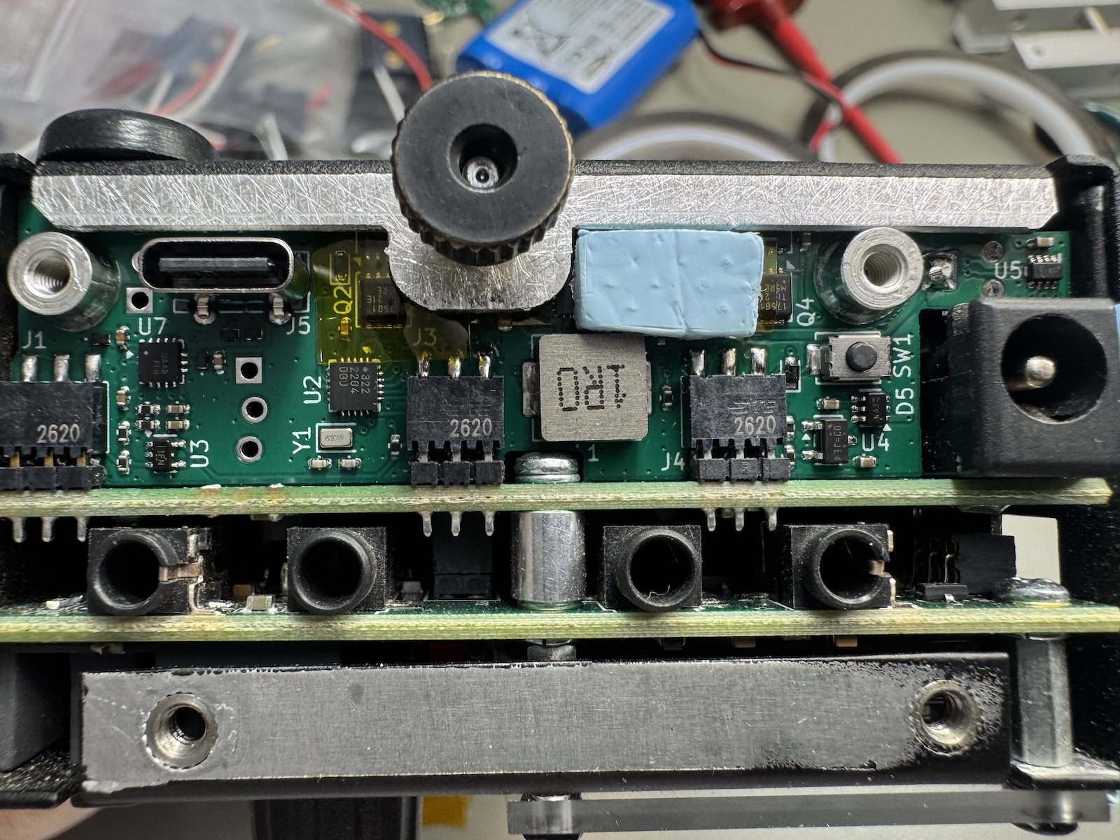
Remove the protective film (if present) from both sides of the thermal pad, then place it over U1, shifted slightly to the right so as not to collide with the back cover
-
Install the replacement side panel using the correct screws for each hole
-
Reinstall the battery
Important
The KXUSBC2 will not work without a battery connected.
-
Enable KXIBC2 in the KX2 menu:
- Turn on the KX2 and go to settings
- Set the KXIBC2 option to "NOR" (enables RTC and battery voltage display)
- Update the KX2 firmware first if the option is not present
Thermistor (optional)
A 10k NTC thermistor can optionally be connected between the marked pads (T and GND) on the backside of the board and attached to the battery pack with tape etc. It will reduce or inhibit charging/discharging if the battery temperature is too high or too low.
Enable thermistor handling via the config button menu or the web-based programmer.
Once installed, head to the user guide to get started.