Introduction
Have you ever forgotten to bring your KX2 charger on a trip, accidentally torn the speaker wires after countless battery removals, or found yourself with a dead phone battery on a summit while the KX2 still had plenty of power? I've managed all three. Each time, I wished the KX2 simply had a USB-C port — no more removing the battery, no special charger to pack, and the ability to top up a phone.
External power banks are awkward when operating handheld with the AX1 and may cause QRM. The KXIBC2 option still requires a specific AC adapter, charges very slowly, and cannot supply power to a phone. Perhaps the best solution until now was to bypass the KX2's built-in reverse-power diodes and connect an external USB-C charger. But with all of these solutions, you can forget something at home that you can't buy on the go.
I prefer fully integrated things that are simple and foolproof to use. So I set out to design an option PCB that installs in place of a KXIBC2 or KXIO2 and adds a bidirectional (dual-role) USB-C port for charging and discharging the internal battery. In homage to Elecraft's naming convention for KX2 options, I call it the KXUSBC2 — an unofficial option.
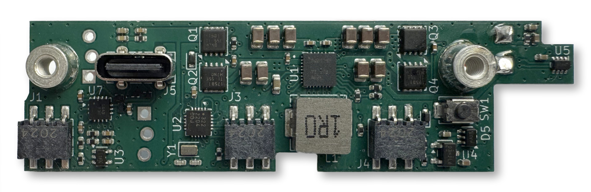
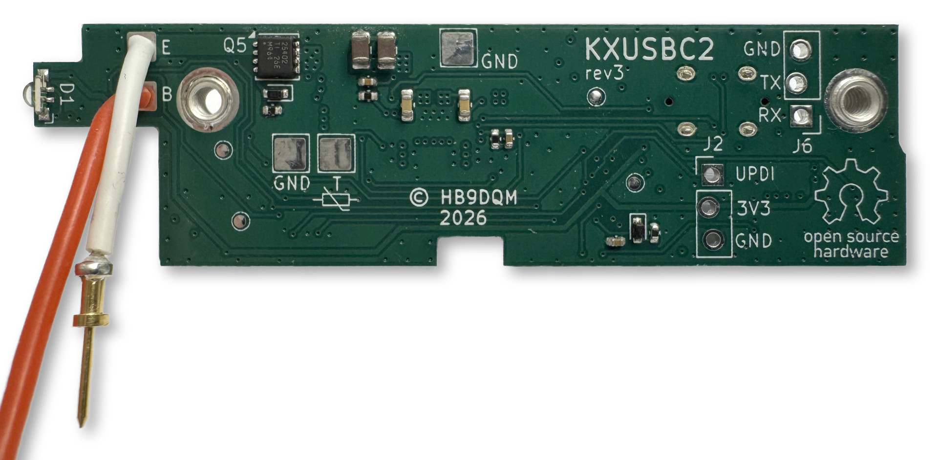
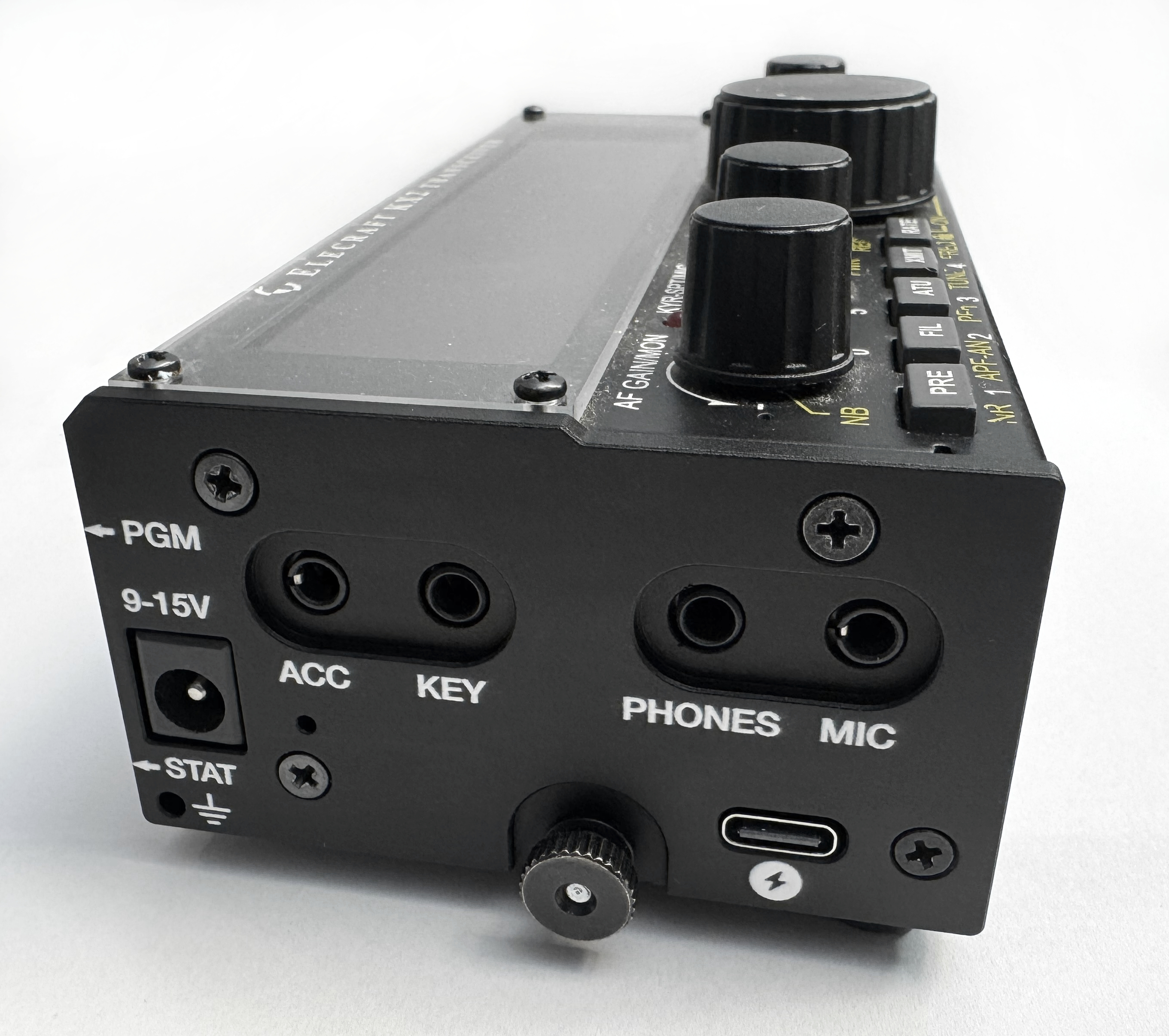
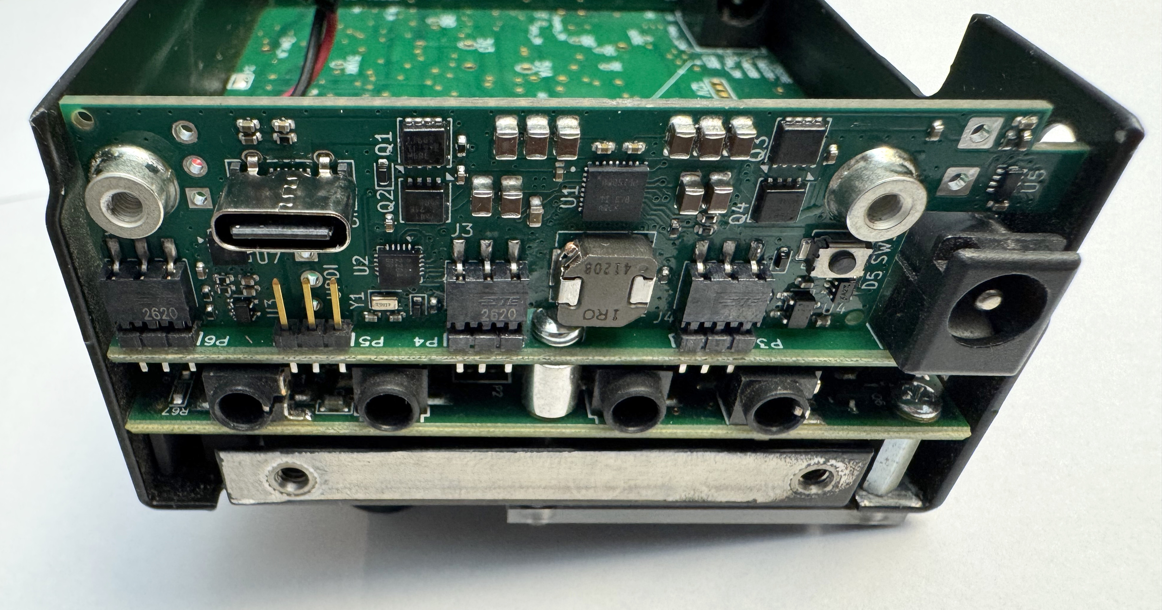
Here is how it looks installed in a KX2, with a custom CNC-machined aluminum side plate for the USB-C port opening:
Features
-
Bidirectional USB-C
Adds a USB-C charging port to the KX2, wired for both charging and discharging.
-
Up to 30 W charging
Charges the internal 3S Li-Ion battery at up to 30 W.
-
Dual-role port (DRP/OTG)
Also charges an external device (phone, GPS, HT etc.) through the same USB-C port, up to 30 W (5–15 V).
-
Dual input
Charges from USB-C or the KX2's DC jack.
-
PD 3.0 / QC / BC1.2
Supports the major USB charging negotiation protocols.
-
QRM-aware
Automatically suspends charging while the KX2 is powered on (so no QRM).
-
Real-time clock
Onboard RTC, temperature-compensated, integrates with the KX2's clock menu.
-
RGB status LED
Status LED plus a config button for on-board settings.
-
Temperature monitoring
Optional battery thermistor input.
-
Battery voltage in KX2 menu
Battery voltage monitor shown in the KX2 menu, like the KXIBC2.
Tech details
- BQ25792 buck-boost battery charger IC
- 1.5 MHz switching frequency
- Quad external power MOSFETs for input switching
- FUSB302B USB-C controller
- ATtiny3226 microcontroller
- Implements the PD protocol stack in firmware
- Current/voltage limits etc. configurable in EEPROM
- Config button for basic settings, trigger a PD role swap, reset
- UPDI debug/programming header
- Serial debug console header
- RTC emulated in MCU (SPI client), backed by crystal, with temperature compensation
- ~60 µA standby current
- 4-layer PCB, components on both sides (min. 0402)
- Replacement aluminum side panel, CNC milled, anodized and silkscreen printed, with USB-C and button pin hole
For more information and the schematic, see the hardware notes.
Installation
Installing the KXUSBC2 is quite simple, and similar to the procedure for the KXIBC2. See installation for details.
Where to buy
While it is possible to have the board and side panel manufactured by a PCB/CNC service like JLC based solely on the design files in this repository, this is not economically viable at very small quantities due to the setup and overhead costs.
Buy a kit
Online shops that sell the KXUSBC2 kit:
If you are interested in selling the KXUSBC2 in your shop and having it listed here, please contact me.
Another option (for people who have some experience ordering and working with PCBs) would be to do group buys, e.g. within a club/association. All information required to do this can be found in the hardware documentation.
I am not selling the KXUSBC2 myself, so please do not send me emails with purchase enquiries.
Firmware updates and configuration
Web-based programmer
There is a web-based programmer that can flash firmware updates and allows easy UI-based configuration of the various settings (current limits etc.). All that is required is a simple UPDI adapter (essentially a USB-to-Serial TTL level adapter) and a browser that supports the Web Serial API.
Development
The schematic/PCB was designed with KiCad, and the firmware was written to be compiled with AVR-GCC. See the hardware notes and firmware notes for details.
Current state of the project
The PCB has gone through four revisions and is now at rev4, which is considered to be production-ready. rev3 and rev4 boards are in use by hundreds of users around the world. The firmware is considered to be complete. See the issues page for any open issues or ideas for future revisions.