Hardware Assembly
Bought a kit?
If you have purchased a ready-made KXUSBC2 kit, this part will already have been completed for you, and you can skip to installation.
Prerequisites
- KXUSBC2 PCB, assembled on both sides
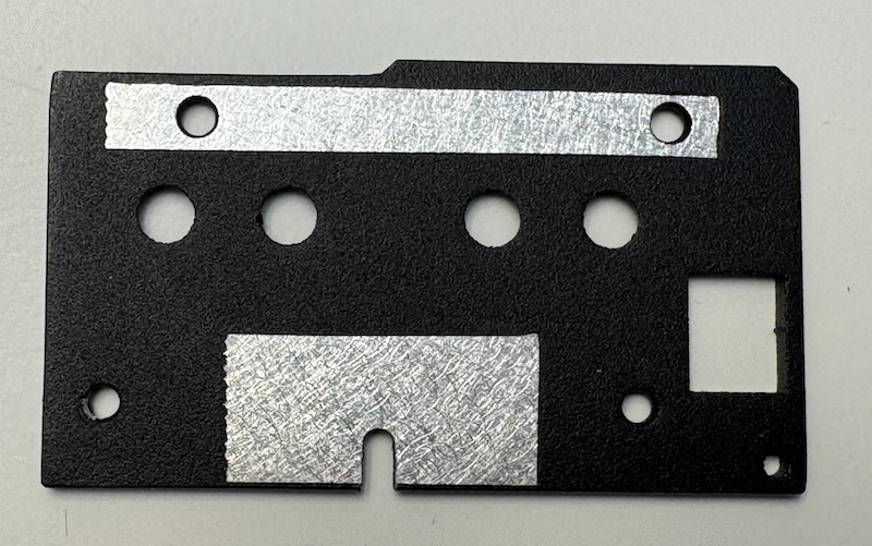
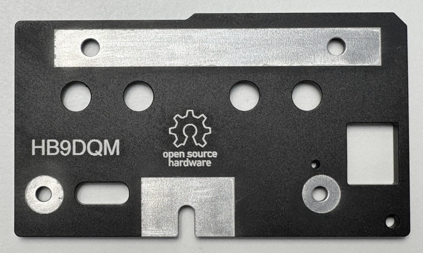
- Replacement left side aluminum panel with USB-C opening
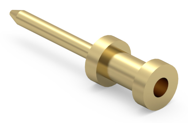
- 2 pcs. mating pins (Mill-Max 3132-0-00-15-00-00-08-0)
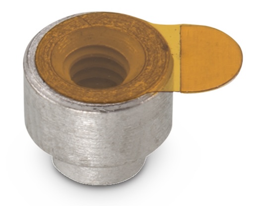
- 2 pcs. standoff M2.5 3 mm height (Würth Electronics 9774030151R, DigiKey 732-7083-1-ND)
- White/red silicone wires (22 AWG), ~50 mm ea.
- Kapton tape
Optional
Preparing the board
Soldering the standoffs
- Place a standoff in a hole on the component side
- Heat with hot air at 200 °C for 30 seconds
- Hold soldering iron to the side of the standoff and pad, and apply solder evenly around the standoff
- Let cool and verify the standoff is centered
- Inspect the bottom side; ideally some solder has migrated through the hole for mechanical strength
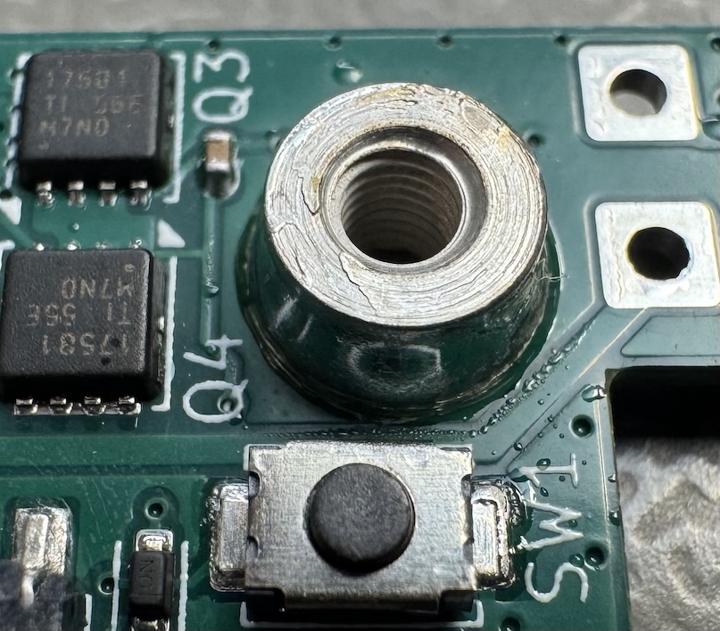
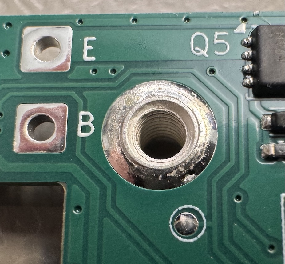
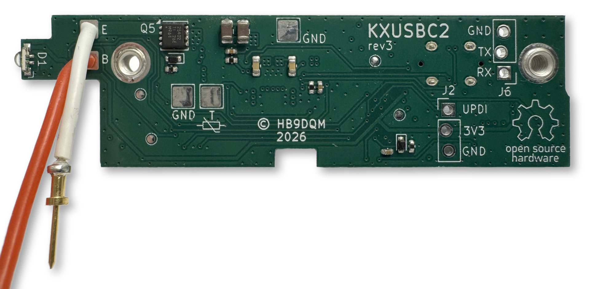
Installing the wires
- Cut ~50 mm pieces of white and red silicone wire
- Strip 3 mm insulation on one end of each wire
- Solder gold mating pins to both wires
- Trim to total length from pin tip:
- E (white): 31 mm
- B (red): 43 mm
- Strip 3 mm from open ends and solder to KXUSBC2 PCB
- Trim excess wire close to board to prevent shorting with the side panel
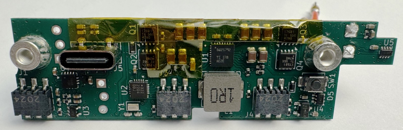
Adding insulating tape
Apply insulating tape (Kapton preferred) to the top edge of the PCB to prevent shorts due to the small clearance to the back cover.
Optional: adding the 3D printed LED diffuser
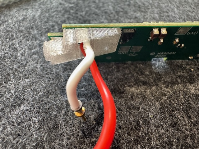
This helps to diffuse the light from the LED, making it more even and reducing glare. It also helps to protect the LED from damage and the cables from strain.
It is recommended to place a small dab of superglue on the PCB to secure the LED diffuser in place.
Handle with care
Be very careful when fitting the part to avoid damaging the LED. See installation for details.
Printing
This should be printed in PETG or ABS, preferably with a transparent or very light coloured filament.
This is a simple part and can be printed with the default settings for your filament. However, to try and get as clear a print as possible I used the following settings:
- Print as hot as the filament allows.
- No fans (to allow it to cool slowly).
- Infill density: 100%.
- Infill pattern: Straight lines.
- No top/bottom layers.
- No supports or brim required.
- Layer height: 0.1mm.
- Line width: 0.36mm.
Preparing the side panel
- Remove black coating from the back side to expose bare metal (where it contacts the KX2 chassis)
- Remove coating around screw holes near USB-C and DC jack for grounding via standoffs (important!)
- Use a Dremel or similar power tool for efficiency (the panel in the photo below was stripped using a laser)